Geometry representations
Signed distance fields
The signed distance function is defined as a function \(S: \mathbb{R}^3 \rightarrow \mathbb{R}\), and returns the signed distance to the object. It has the additional property
The normal vector is always
EBGeometry uses the following convention for the sign:
which means that the normal vector \(\mathbf{n}\) points away from the object.
Implicit functions
Like distance functions, implicit functions also determine whether or not a point \(\mathbf{x}\) is inside or outside an object. Signed distance functions are also implicit functions, but not vice versa. For example, the signed distance function for a sphere with center \(\mathbf{x}_0\) and radius \(R\) can be written
An example of an implicit function for the same sphere is
An important difference between these is the Eikonal property in Eq. 1, ensuring that the signed distance function always returns the exact distance to the object. Signed distance functions are more useful objects, but many operations (e.g. CSG unions) do not preserve the signed distance property (but still provide bounds for the signed distance).
DCEL
Principle
EBGeometry uses a doubly-connected edge list (DCEL) structure for storing surface meshes.
The DCEL structures consist of the following objects:
Planar polygons (facets).
Half-edges.
Vertices.
As shown in Fig. 1, half-edges circulate the inside of the facet, with pointer access to the next half-edge. A half-edge also stores a reference to its starting vertex, as well as a reference to its pair-edge. From the DCEL structure we can obtain all edges or vertices belonging to a single facet by iterating through the half-edges, and also jump to a neighboring facet by fetching the pair edge.
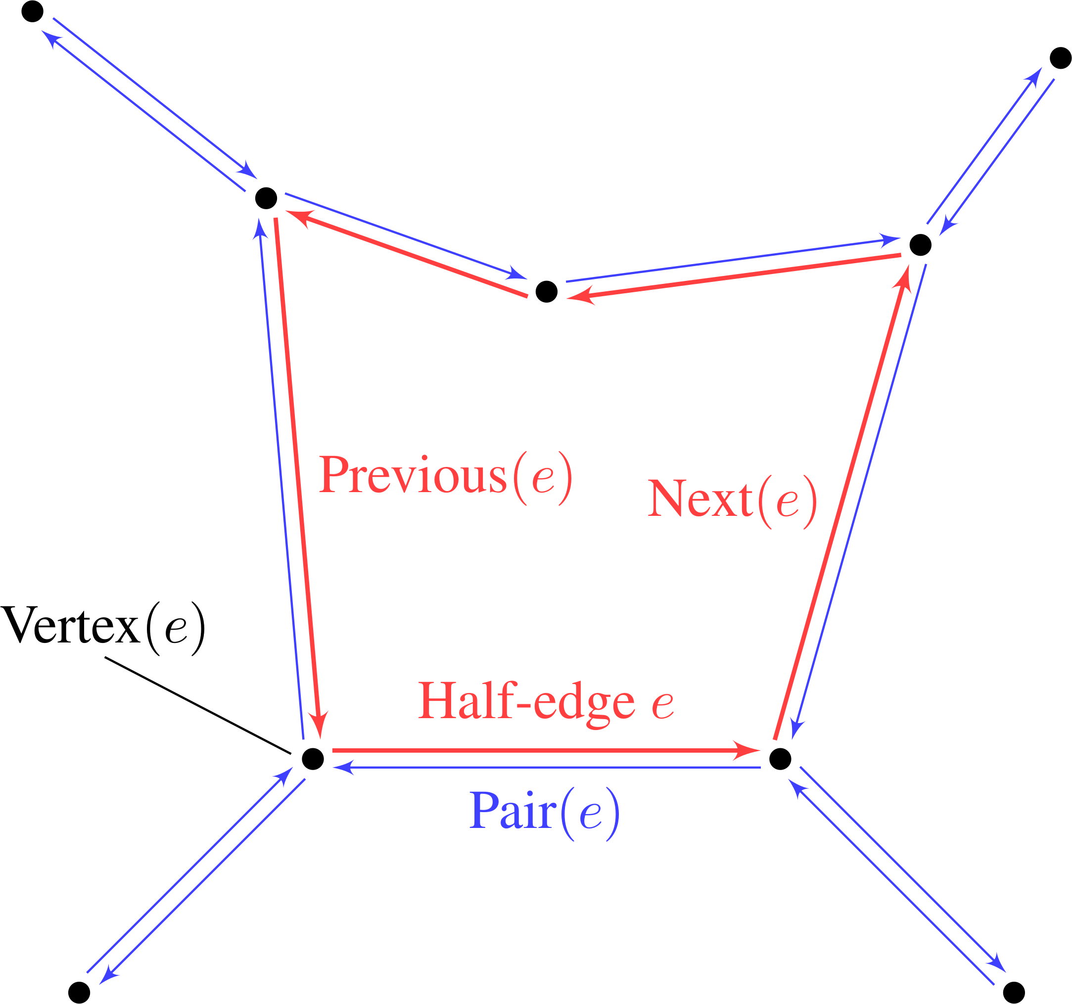
Fig. 1 DCEL mesh structure. Each half-edge stores references to next half-edge, the pair edge, and the starting vertex. Vertices store a coordinate as well as a reference to one of the outgoing half-edges.
In EBGeometry the half-edge data structure is implemented in its own namespace.
This is a comparatively standard implementation of the DCEL structure, supplemented by functions that permit signed distance computations to various features on such a mesh.
Important
A signed distance field requires a watertight and orientable surface mesh. If the surface mesh consists of holes or flipped facets, neither the signed distance or implicit function exist.
Signed distance
The signed distance to a surface mesh is equivalent to the signed distance to the closest polygon face in the mesh. When computing the signed distance from a point \(\mathbf{x}\) to a polygon face (e.g., a triangle), the closest feature on the polygon can be one of the vertices, edges, or the interior of the polygon face, see Fig. 2.
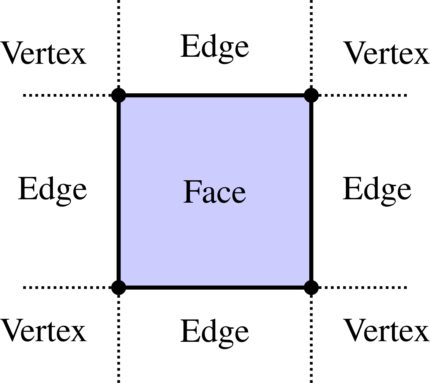
Fig. 2 Possible closest-feature cases after projecting a point \(\mathbf{x}\) to the plane of a polygon face.
Three cases can be distinguished:
Facet/Polygon face.
When computing the distance from a point \(\mathbf{x}\) to the polygon face we first determine if the projection of \(\mathbf{x}\) to the face plane lies inside or outside the face. This is more involved than one might think, and it is done by first computing the two-dimensional projection of the polygon face, ignoring one of the coordinates. Next, we determine, using 2D algorithms, if the projected point lies inside the embedded 2D representation of the polygon face. Various algorithms for this are available, such as computing the winding number, the crossing number, or the subtended angle between the projected point and the 2D polygon.
Tip
EBGeometryuses the crossing number algorithm by default.If the point projects to the inside of the face, the signed distance is just \(\mathbf{n}_f\cdot\left(\mathbf{x} - \mathbf{x}_f\right)\) where \(\mathbf{n}_f\) is the face normal and \(\mathbf{x}_f\) is a point on the face plane (e.g., a vertex). If the point projects to outside the polygon face, the closest feature is either an edge or a vertex.
Edge.
When computing the signed distance to an edge, the edge is parametrized as \(\mathbf{e}(t) = \mathbf{x}_0 + \left(\mathbf{x}_1 - \mathbf{x}_0\right)t\), where \(\mathbf{x}_0\) and \(\mathbf{x}_1\) are the starting and ending vertex coordinates. The point \(\mathbf{x}\) is projected to this line, and if the projection yields \(t^\prime \in [0,1]\) then the edge is the closest point. In that case the signed distance is the projected distance and the sign is given by the sign of \(\mathbf{n}_e\cdot\left(\mathbf{x} - \mathbf{x}_0\right)\) where \(\mathbf{n}_e\) is the pseudonormal vector of the edge. Otherwise, the closest point is one of the vertices.
Vertex.
If the closest point is a vertex then the signed distance is simply \(\mathbf{n}_v\cdot\left(\mathbf{x}-\mathbf{x}_v\right)\) where \(\mathbf{n}_v\) is the vertex pseudonormal and \(\mathbf{x}_v\) is the vertex position.
Normal vectors
The normal vectors for edges \(\mathbf{n}_e\) and vertices \(\mathbf{n}_v\) are, unlike the facet normal, not uniquely defined. For both edges and vertices we use the pseudonormals from [1]:
where \(f\) and \(f^\prime\) are the two faces connecting the edge. The vertex pseudonormal is given by
where the sum runs over all faces which share \(v\) as a vertex, and where \(\alpha_i\) is the subtended angle of the face \(f_i\), see Fig. 3.
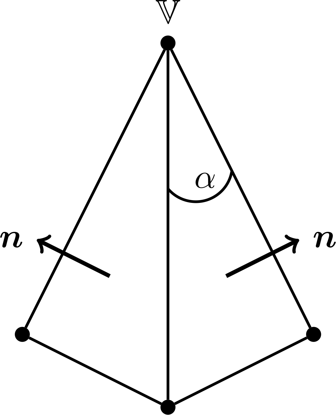
Fig. 3 Edge and vertex pseudonormals.
Triangles
EBGeometry also supports using direct triangles rather than DCEL polygons.
In this case the user can parse his/her files and ask for triangle description rather than a DCEL description.
Internally, triangles are represented as pseudo-triangles that contain normal vectors on both the edges and vertices, completely similar to a DCEL polygon.
Bounding volume hierarchies
Bounding volume hierarchies (BVHs) are tree structures where the regular nodes are bounding volumes that enclose all geometric primitives (e.g. polygon faces or implicit functions) further down in the hierarchy. This means that every node in a BVH is associated with a bounding volume. The bounding volume can, in principle, be any type of volume. There are two types of nodes in a BVH:
Regular/interior nodes. These do not contain any of the primitives/objects, but store references to subtrees (aka child nodes).
Leaf nodes. These lie at the bottom of the BVH tree and each of them contains a subset of the geometric primitives.
Fig. 4 shows a concept of BVH partitioning of a set of triangles. Here, \(P\) is a regular node whose bounding volume encloses all geometric primitives in its subtree. Its bounding volume, an axis-aligned bounding box or AABB for short, is illustrated by a dashed rectangle. The interior node \(P\) stores references to the leaf nodes \(L\) and \(R\). As shown in Fig. 4, \(L\) contains 5 triangles enclosed by another AABB. The other child node \(R\) contains 6 triangles that are also enclosed by an AABB. Note that the bounding volume for \(P\) encloses the bounding volumes of \(L\) and \(R\) and that the bounding volumes for \(L\) and \(R\) contain a small overlap.
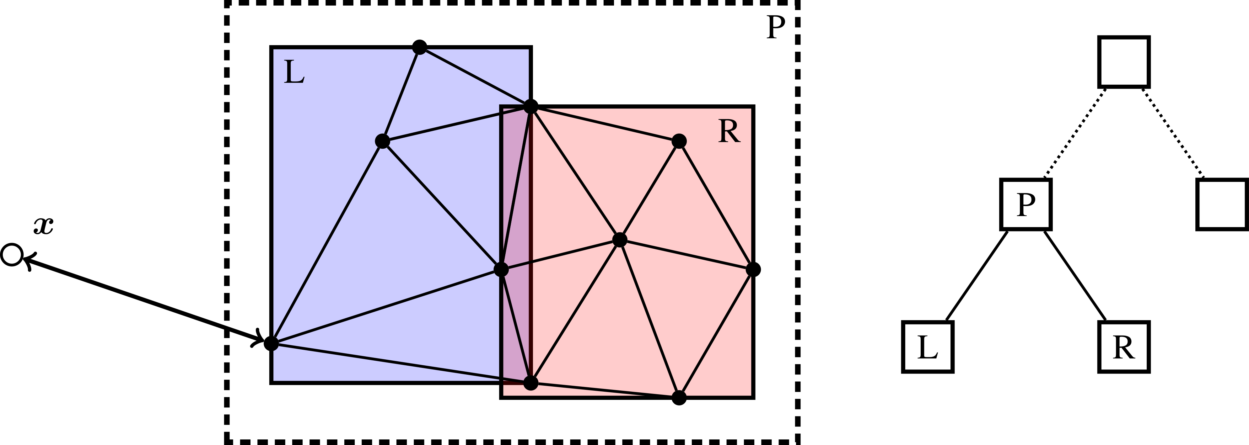
Fig. 4 Example of BVH partitioning for enclosing triangles. The regular node \(P\) contains two leaf nodes \(L\) and \(R\) which contain the primitives (triangles).
There is no fundamental limitation to what type of primitives/objects can be enclosed in BVHs, which makes BVHs useful beyond triangulated data sets. For example, analytic signed distance functions can also be embedded in BVHs, provided that we can construct bounding volumes that enclose them.
Important
EBGeometry is not limited to binary trees, but supports \(k\) -ary trees where each regular node has \(k\) child nodes.
Construction
BVH construction is fairly flexible. For example, the child nodes \(L\) and \(R\) in Fig. 4 could be partitioned in any number of ways, with the only requirement being that each child node gets at least one triangle/primitive.
Although the rules for BVH construction are highly flexible, performant BVHs are completely reliant on having balanced trees with the following heuristic properties:
Tight bounding volumes that enclose the primitives as tightly as possible.
Minimal overlap between the bounding volumes.
Balanced, in the sense that the tree depth does not vary greatly through the tree, and there is approximately the same number of primitives in each leaf node.
Construction of a BVH is usually done recursively, from top to bottom (so-called top-down construction).
Alternative construction methods also exist, but are not used in EBGeometry.
In this case one can represent the BVH construction of a \(k\) -ary tree is done through a single function:
where \(\vec{O}\) is an input a list of objects/primitives, which is partitioned into \(k\) new list of primitives. Note that the lists \(\vec{O}_i\) do not contain duplicates, there is a unique set of primitives associated in each new leaf node. Top-down construction can thus be illustrated as a recursive procedure:
topDownConstruction(Objects):
   partitionedObjects = Partition(Objects)

   forall p in partitionedObjects:
      child = insertChildNode(newObjects)

      if(enoughPrimitives(child)):
         child.topDownConstruction(child.objects)
In practice, the above procedure is supplemented by more sophisticated criteria for terminating the recursion, as well as routines for creating the bounding volumes around the newly inserted nodes.
Bottom-up construction is also possible, in which case one constructs the leaf nodes first, and then merge the nodes upward until one reaches a root node.
In EBGeometry, bottom-up construction is done by means of space-filling curves (e.g., Morton codes).
Tree traversal
When computing the signed distance function to objects embedded in a BVH, one takes advantage of the hierarchical embedding of the primitives. Consider the case in Fig. 5, where the goal of the BVH traversal is to minimize the number of branches and nodes that are visited. For the traversal algorithm we consider the following steps:
When descending from node \(P\) we determine that we first investigate the left subtree (node \(A\)) since its bounding volume is closer than the bounding volumes for the other subtree. The other subtree will is investigated after we have recursed to the bottom of the \(A\) subtree.
Since \(A\) is a leaf node, we compute the signed distance from \(\mathbf{x}\) to the primitives in \(A\). This requires us to iterate over all the triangles in \(A\).
When investigating the other child node of \(P\), we find that the distance to the primitives in \(A\) is shorter than the distance from \(\mathbf{x}\) to the bounding volume that encloses nodes \(B\) and \(C\). This immediately permits us to prune the entire subtree containing \(B\) and \(C\).
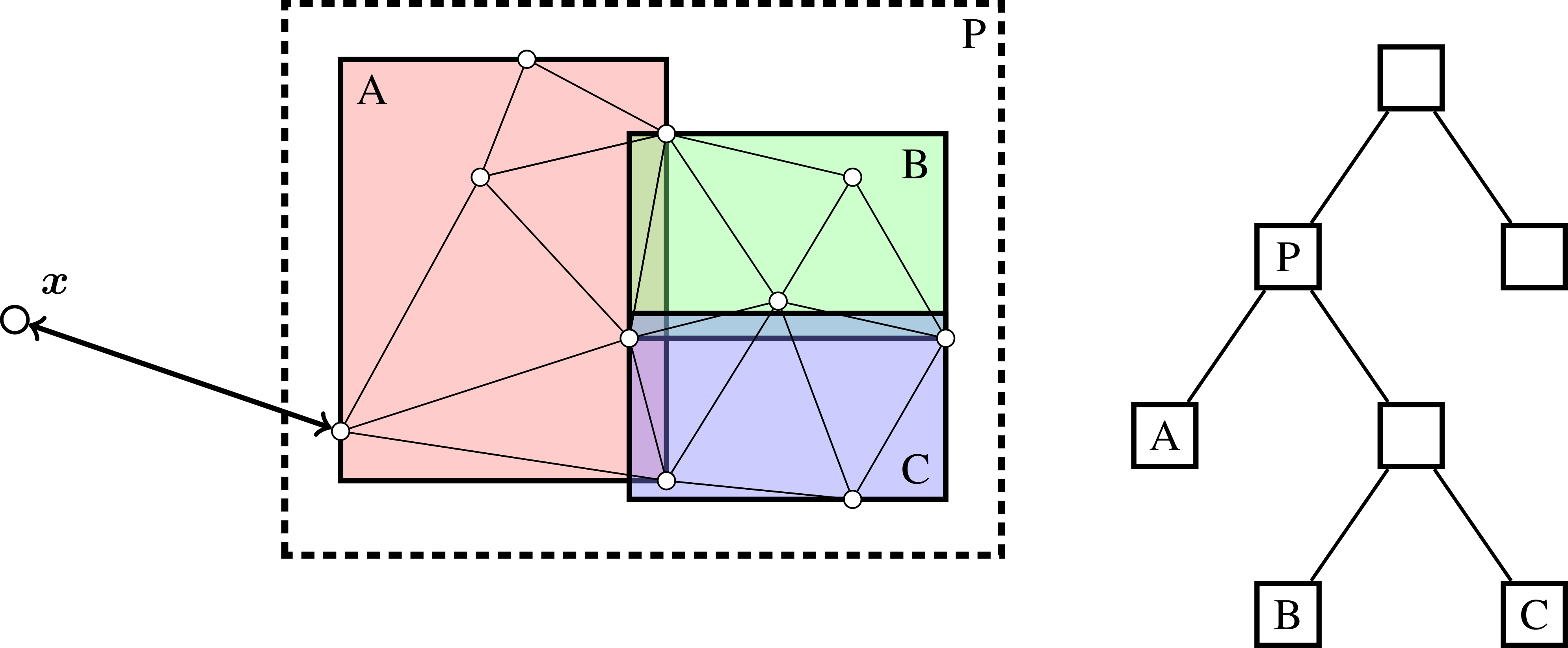
Fig. 5 Example of BVH tree pruning.
Warning
BVH traversal has \(\log N\) complexity on average. However in the worst case the traversal algorithm may have linear complexity if the primitives are all at approximately the same distance from the query point. For example, it is necessary to traverse almost the entire tree when one tries to compute the signed distance at the origin of a tessellated sphere since all triangles and their bounding volumes are approximately at the same distance from the center.
Other types of tree traversal (that do not compute the signed distance) are also possible.
EBGeometry supports a fairly flexible approach to the tree traversal and update algorithms such that the user is permitted to use the hierarhical traversal algorithm also for other types of operations (e.g., for finding all facets within a specified distance from a point).
Octree
Octrees are tree-structures where each interior node has exactly eight children. Such trees are usually used for spatial partitioning. Unlike BVH trees, the eight child nodes have no spatial overlap.
Octree construction can be done in (at least) two ways:
In depth-first order where entire sub-trees are built first.
In breadth-first order where tree levels are added one at a time.
EBGeometry supports both of these methods.
Octree traversal is generally speaking quite similar to the traversal algorithms used for BVH trees.
Constructive solid geometry
Basic transformations
Implicit functions, and by extension also signed distance fields, can be manipulated using basic transformations (like rotations).
EBGeometry supports many of these:
Rotations.
Translations.
Surface offsets.
Shell extraction.
Mollification (e.g., smoothing)
… and others.
Warning
Some of these operations preserve the signed distance property, and others do not.
Combining objects
EBGeometry supports standard operations in which implicit functions can be combined:
Union.
Intersection.
Difference.
Some of these CSG operations also have smooth equivalents, i.e. for smoothing the transition between combined objects.
Fast CSG operations are also supported by EBGeometry, e.g. the BVH-accelerated CSG union where one uses the BVH when searching for the relevant geometric primitive(s).
This functionality is motivated by the fact that a CSG union is normally implemented as \(\min\left(I_1, I_2, I_3, \ldots,I_N\right)\), which has \(\mathcal{O}\left(N\right)\) complexity when there are \(N\) objects.
BVH trees can reduce this to \(\mathcal{O}\left(\log N\right)\) complexity.